Thursday, September 30, 2010
Wednesday, September 29, 2010
September Log
9/27
Looking back on the weekend, I uploaded an updated background, completed my alternate solutions, and uploaded the posts. Today, I started to read over the comments, followed by updating the alternate solutions by posting up the first entry for my first alternate solution. Need to complete the other two solution abstracts and provide an introduction and conclusion.
9/28
Considering I didn't get much done yesterday, and realize my blog is lacking overall I tried to locate some more pictures for my background page. Found about 20 images ranging from users to ROV application and uses. Lastly, added the second's solutions abstract. NEED TO FINISH.
9/29
From the gun, started working on the introduction, the third solution's abstract and conclusion. Looked over past posts to evaluate where I stand. Realize I need to add some more. Reminded that I need to complete my log, so I am posting NOW.
Saturday, September 25, 2010
Alternate Solutions
Introduction
This section has been dedicated to the outlining and description of my alternate solutions. Attached are three distinct alternate solutions along with a description providing the specificaitons and capabilities. Furthermore, each solution has elementary criticisms to show which system works best, because no design will be able to attain maximum points in each category, due to the trade-offs that each component of the vehicle structure system has. Nevertheless, each and every design is viable and is able to perform the tasks. Whether each design can perform each task at a high level is another question.

Solution #1 (Catamaran)
The following design's dimensions is: 18 inches long, 12 inches wide, and 10 inches tall. The general structure of the ROV takes the shape of a catamaran that one might find in a sailboat design. The basic design consists of two riggers that are connected by a flat platform on top. The plan is to use alumunim sheeting for the riggers and place a polyethylene board on top. Metal brackets would be used to attach cameras, the manipulator, and thrusters. The concept of the design is one that is compact and allows the ROV to slide over object, which would allow it to hover over objects, especially in the sensor task where the ROV might need to hover over the sounding devices in order for the hydrophone to pick up readings. The small size would be ideal for manuevering in the tunnel. Ultimately, this first solution fits the specifications that could solve the problems.

The following design's dimesion is: 18 inches long, 10 inches wide, and 10 inches high. The generally shape of the design is a snowmobile/skid. It involves a stable platform that is derived from the skid design. Additionally, the skid platform allows the vehicle to manuever over objects. This capability allows the vehicle to position itself in various positions in order to manipulate objects in awkward areas. The slanted front side creates a hydrodynamic approach as it plows through the water. Along with the ballast area, the cameras would be able to be housed on the wall of the front panel. The hydrophone can be attached on the underside of the tank. And to provide maximum thrust, the thruster may be attacked to the sides of the ballast tank as well as the back. Lastly, the design would take on the use of two materials. The skid would either be constructed using PVC piping or polyethylene cut outs. The tank would be constructed of a aluminum body that would be Tig welded to secure the adjoing edges.
Solution #2 (Snow Mobile/Skid)

Solution #3 (Box)
This simple design is reminiscent of many larger ROVs. With a structure that takes on the shape of a rectangular prism, the vehicle is one that is very stable. Additionally, the design is flexible, meaning that it allows for many layouts. In general, it is understood that the manipulator will be placed in the front. Also, thrusters may be placed along the sides, in the back, and placed in a vertical orientation on top. Furthermore, a permanent fixture of the structure is the ballast system. In front of the tank, the camera and hydrophone may be positioned facing the manipulator. Offering key specifications such as stability and flexibility, this design is optimal as a basic design. However, due to its size and layout, this vehicle would have to drive like a car, and therefore take special caution when removing the pins, as well as removing the crustaceans. Again, the inability to "truck" over objects in order to hover over makes it difficult to complete some tasks such as the hyrdophone testing. However, it does offer a design that has had luck in the industry. Regarding luck in the industry, the ROV would be constructed out of a PVC frame using similar to many past designs that have been used at the MATES ROV Competition.
Ultimatlely, the following designs are viable solutions that help solve the situation of completeing tasks, such as retrieving crustaceans, removing pins, and taking hyrdophone readings. Additionally, the designs meet the specifications that have been outlined, which is crucial considering that the specifications are define the crucial elements that are needed to perform at maxiumum performance. In the end, the following designs, although all are viable, need to be reevaluated to determine which is the optimal design. The process of deciding will involve reviewing the specifications, as well as incorporating the systems of my partners (claw and electrical and propulsion). Along with those pieces of input, the design will be sent for evaluation by a professional in the field of marine technology and as well as a packaging engineer. Eventually, with further conclusive research, my team and I will be able to make the right decision with the right knowledge as we weigh out each design against multiple specifications using a specification grid.
Monday, September 20, 2010
Testing Procedure
Ultimately, the goal of the Capstone Design Project is to complete the design brief, which is to essentially to construct a functioning ROV. In the end, the ROV should be able to achieve basic functions such as maneuvering along an X-Y-Z plane, as well as manipulating objects and making observations. Specifically regarding the vehicle structure system, the ROV needs to meet standards as listed in the specifications, such as being neutrally buoyant or being able to maneuver through the 80cm X 80cm tunnel. The thrusters will be tested on the basis of ability to move water effectively. Additionally it must be able to be controlled effectively. The manipulator must be able to manipulate the pin, Agar, and the crustaceans. Essentially, each component should be tested before the competition to work out the kinks.


Testing Procedure (Team)

Testing Procedure (Individual)
Exploratory Testing:
Before moving too far into the project, the mission team needs to use his pre-existing knowledge as well as research to ensure that what has been conceptualized has a possibility to work. This is probably the most important part of the testing period, as the outcome of the test results in the future of the project. During this period, it is essential that the mission team is completely cooperative. Additionally, they must be in constant communication in order to update each other on their developmental progress. Furthermore, the engineers of each system should be in contact with their mentors in order to receive feedback on their design. Ultimately, the knowledge from the mentor and group members which help to settle the basis for each design leads to a conclusive result.

Assessment Testing:
Moving past the developmental work of drawing, the engineer is starting to model the production product. This is the first time the engineer would be able to fully comprehend the design. Through modeling, the engineer should use materials that are similar if not identical to the final solution. In the case of the ROV, the layout should be understood from the design. In some cases, this testing procedure may need to be reevaluated in order to make a complete judgment call.


Validation Testing:
In the final stage of the project, this will essentially be the concluding test, otherwise known as the competition. It will validate whether or not is performed up to the standards spelled out or expected. After much design and prototyping, most if not all the kinks should have been worked out. The ROV at this point should be able to work as a full system.
Testing Procedure (Team)
1. Find an area that is comfortable and clear of potential hazards.
2. Unpackage and inspect the system: vehicle, control console, tether and reel, spares/tool kit, monitor.
4. Complete the dry land pre-dive inspection (check the thrusters, tether, control system, manipulator, tool, structure).
5. Deploy the ROV for testing.
6. Test the horizontal propulsion for forward, backwards, left then right to ensure that the thrusters operates correctly.
7. Test the vertical propulsion to ensure that the vertical thrusters operate correctly.
8. Test the ballast.
10. Test the cameras and/or tools.
11. Test the manipulator.
12. Post-dive inspection.
13. Rinse and wipe ROV.
14. Store ROV.

Testing Procedure (Individual)
1. Attach the thrusters, camera and/or tools, and manipulator to determine if the vehicle can hold all the components.
2. Identify if the structure meets all the specifications and limitations.
-Is the ROV able to be transported by the mission team?
-Is it a flexible, stable platform?
-Propellers clear of obstruction?
-No hazardous materials?
3. Pre-dive inspection.
4. Deploy the ROV.
5. Post-dive inspection
5. Post-dive inspection
Remotely Operated Vehicle Observation Sheet
Exploratory Testing:
1. Is the ROV design conducive to the fresh, chlorinate water environment?
Yes No
2. Is the ROV design able to enter and maneuver through a tunnel 80 cm x 80 cm?
Yes No
3. Is the ROV design able to be transported by the mission team?
Yes No
4. Is the ROV design stable?
Yes No
5. Is the ROV design neutrally buoyant?
Yes No
6. Are the propellers clear of obstruction?
Yes No
Assessment Testing:
1. From initial observations of the model, does the ROV design meet the specifications?
Yes No
2. Does initial handling of the model give a sense of durability?
Yes No If no, provide suggestions to improve the design. ________________
3. Will it be possible to successfully seal the housing?
Yes No
4. Are the skids securely attached to the housing?
Yes No
5. Does the layout provide room to attach the thrusters, thermometer, hydrophone, and claw?
Yes No
Specifications & Limitations
Specifications
- Must be able to function in fresh, chlorinated water; The water should be considered conductive of electrical currents
- Must be capable of operating in a minimum pool depth of 1.2 meters. The maximum depth is 4 meters.
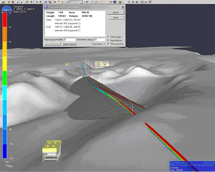
- Must be able to enter and maneuver through a tunnel 80 cm x 80 cm
- Must be a highly portable system; Must be able to be transported by the mission team
- Optimized small design and layout (flexible, stable platform) – balanced, serviceable, low drag
- Must be neutrally buoyant
- Must have vacuum sealed housing
- Keep the propellers clear of obstructions at all times
- No hazardous materials
- Must be able to move in all axis; vectored thruster configuration
- Must be able to accept thrusters, wide range of cameras, sensors, tools and more
Limitations
- must abide by MATES ROV Competition Rules (Ranger Class)
- no commercially-sourced systems
- must be a safe vehicle; must pass a safety inspection
- must be capable of operating in a minimum pool depth of 1.2 meters. The maximum depth is 4 meters.
- must be able to enter and manuever through a tunnel 80 cm x 80 cm
- must be a highly portable system; Must be able to be transported by the mission team
 |
| Figure 3: MATE International ROV Safety Check |
Design Brief
Team
Design and develop a fully functioning Remotely Operated Vehicle (ROV) for the 2011 MATES ROV Competition to be operated by a mission team in a fresh, chlorinated water pool while performing a checklist of tasks, including maneuvering through a 80cm X 80cm tunnel, manipulating objects (grabbing three crustaceans, scooping 100mL of Agar, and pulling out PVC pins), and making observations.
 |
| Figure 2: The MATES ROV Competition logo. |
Individual Component
Design and build a neutrally buoyant structure of a Remotely Operated Vehicle (ROV) that employs a stable platform design, which incorporates the ballast and propulsion system, manipulator, camera, hydrophone, and sensors that will ultimately be operated by a mission team member in a fresh, chlorinated water pool in order to maneuver and complete a checklist of tasks.
Background


Marine Academy of Science & Technology (MAST) students have the option to design and develop a Remotely Operated Underwater Vehicle (ROV)1 for the MATES ROV Competition, as an aspect of the Systems Engineering II curriculum – the Capstone Design Project. Considering that the definition of Systems Engineering is to address the integration of the many subsystems that comprise the larger system, students work as system engineers on three-man teams to design and integrate various components (vehicle structure, propulsion/electrical system, manipulator system) that must function together in an effective and efficient manner in order to develop the “big picture” (design and develop a ROV). In the end, the ROV project results from the MATE Center and the Marine Technology Society’s ROV Committee, which organizes the annual MATE ROV Competition. The competition aims to simulate real world ROV application by having students assemble an ROV to cover tasks from deploying instruments, take sensor readings, and collect samples of geologic features, as well as organisms. Precisely, the event replicates the Loihi seamount, an active undersea volcano that rises more than 3,000 meters above the seafloor.


1 A Remotely Operated Underwater Vehicle (ROV) is fundamentally an underwater robot that is controlled by an operator that is independent of the vehicle, from the surface that allows the operator to remain out of harm’s way while the ROV works in the hazardous environment below. The total ROV system is comprised of the vehicle, control, umbilical cord (tether), and power supplies. Basic features on an ROV include: thrusters, cameras, various sensors and/or tools. ROVs can vary in size depending on the work, from small vehicles for simple observation up to complex work systems, which can have several manipulators, cameras, tools, and other equipment.
 |
| Figure 1: An industrial Remotely Operated Vehicle (ROV). |
The basic concept of designing ROVs was to eliminate the human factor in underwater tasks. First developed for industrial purposes, such as inspections of pipelines, ROVs are now used for many applications, many of them being scientific. They have become an essential part of progressing industries and science.
In this specific situation, the testing will be conducted in a freshwater pool. The objectives of the competition include basic camera observations, as well as performing tasks such as navigating through a tunnel and turning, and grabbing objects and relocating them.


Subscribe to:
Posts (Atom)